Cobot Scanner
Installation, operation, integration, and technical information for the Cheetah CE-101100 Cobot Scanner.
Cobot Scanner
CE-101100
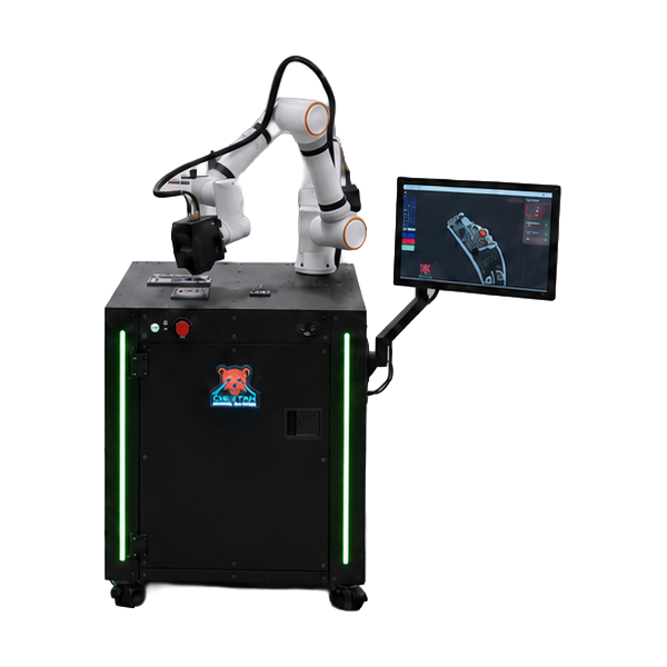
The Cobot Scanner is Cheetah's flexible inspection platform for parts that require multiple viewpoints. A collaborative robot moves a 3D laser scanner around the part, combining measurements from different positions into a larger representation. This allows the system to inspect complex geometry and measure relationships between features that cannot fit within a single scanner field of view.
This page is the primary hardware manual for the current Cobot Scanner platform. It covers the physical workstation, installation, electrical power, operator controls, customer-facing hardware interfaces, safety and I/O integration, and basic care of the system.
Application-specific fixtures, sensors, and other Cheetah-installed hardware may vary between systems and are documented separately when required. Detailed operation of the Cheetah software, inspection programs, and developer interfaces is covered in the corresponding software and developer documentation.
System Identification#
Each Cobot Scanner has a unique system serial number used to identify the machine for service, support, configuration records, and replacement parts.
The serial number is marked in two locations:
- Chassis marking - permanently laser cut into the chassis inside the front storage cabinet. Open the storage door and look at the right-hand side of the chassis. Note: On some legacy systems, the marking is located on the upper interior surface of the storage area and can be seen by looking upward.
- Identification label - located on the inside of the control cabinet door and shows both the system serial number and system part number.
System Layout#
The Cobot Scanner is organized around a common workstation with inspection hardware above, operator controls at the front, and integration and control hardware at the rear.
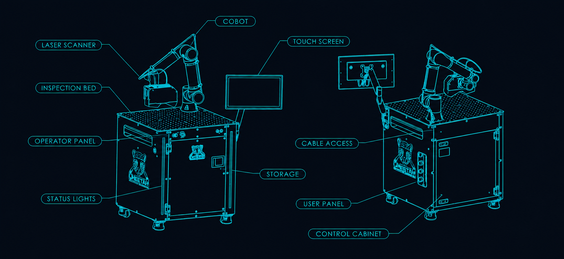
The major workstation areas are:
- Cobot - positions the laser scanner around the inspection area
- Laser scanner - captures three-dimensional surface measurements of the part
- Inspection bed - configurable mounting surface for the robot, fixtures, and application-specific hardware
- Touchscreen - industrial display running the Cheetah operator interface
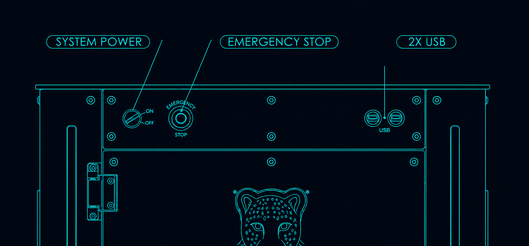
- Operator panel - main controls for system power, emergency stop, and front USB access
- Status lights - front RGB light strips for visible machine-state indication
- Storage cabinet - front-access storage for fixtures, tools, reference parts, and accessories
- User expansion panel - customer-facing interface for networking, USB, safety, and discrete I/O
- Cable access panel - removable panel providing access to the control cabinet cable-entry system
- Control cabinet - rear-access electrical cabinet containing the system controls and electronics
Receiving & Unboxing#
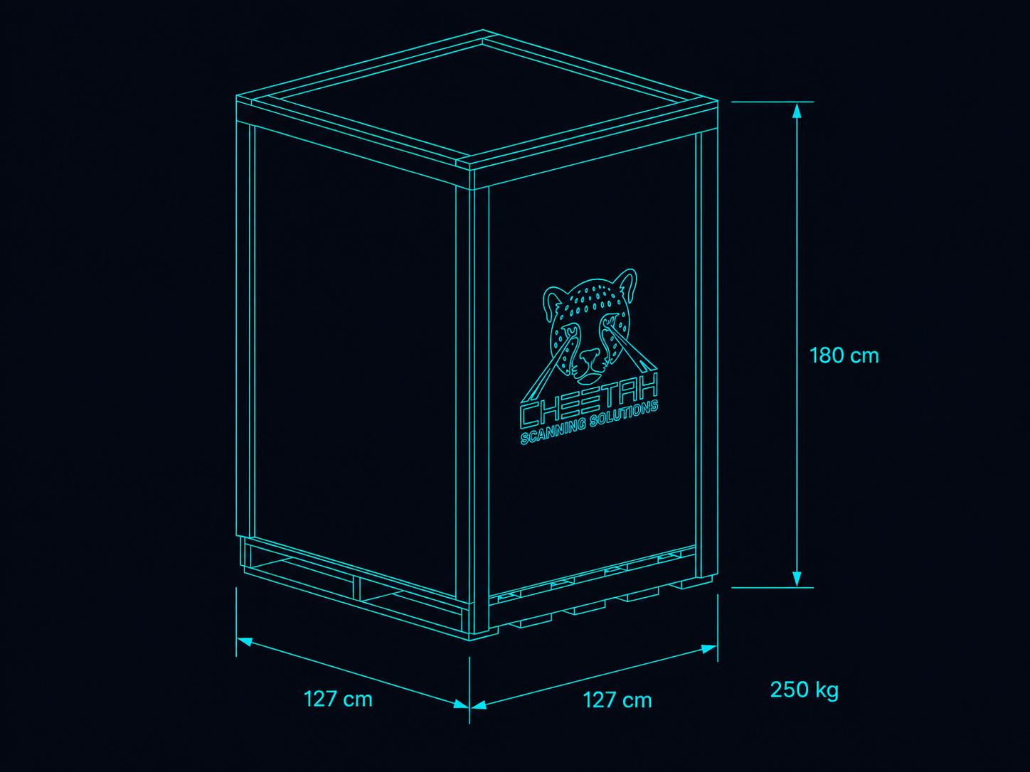
The Cobot Scanner ships secured to a wooden pallet inside a protective crate.
Upon receipt:
- Inspect the crate for visible shipping damage.
- Move the crated workstation to the installation area using a pallet jack or forklift.
- Remove the outer packaging and protective materials.
- Remove the screws securing the red shipping mounts to the wooden pallet. Leave the mounts attached to the workstation.
- Using a forklift, lift the workstation from the pallet and place it on the floor.
- Remove the red shipping mounts from the workstation.
- Verify that the workstation and included accessories are present and undamaged.
- Retain the shipping mounts and packaging if the workstation may need to be moved again.
Mechanical Installation#
Positioning and Leveling#
Install the workstation on a stable floor with sufficient access for operation and service.
Once removed from the pallet, the workstation can be rolled into its final position on the integrated casters.
After positioning, use the leveling feet to raise the workstation off the casters and onto the rubber pads. Adjust the feet until the workstation is stable and level.
Clearances#
Allow space around the workstation for:
- Opening the rear control cabinet door
- Accessing the touchscreen and operator panel
- Accessing the user expansion panel
- Loading and unloading parts and fixtures
- Operating the robot safely within the intended work area
Note: Depending on the application, the robot may extend beyond the normal workstation footprint during operation. Application-specific clearance requirements will be provided by Cheetah for each configured system.
Touchscreen Installation#
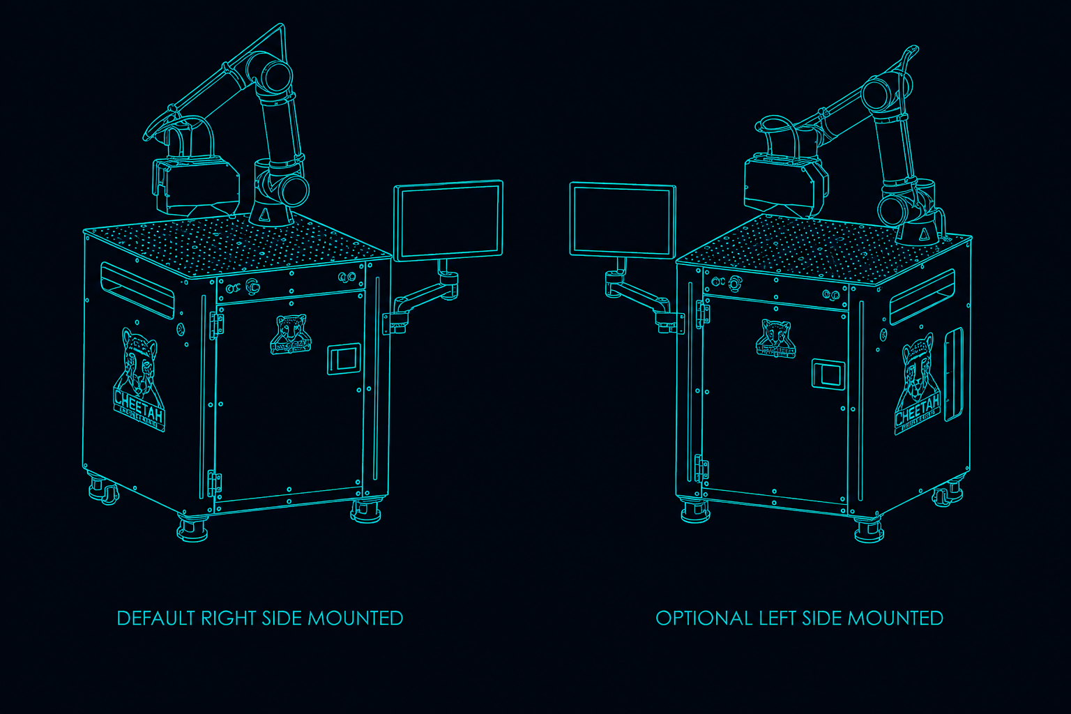
The touchscreen mounts to an articulated arm.
For the Cobot Scanner, the touchscreen arm is mounted on the right side by default, but can be installed on the left when required by the installation. After mounting, route and secure the cables so the display can move freely without interference.
Electrical Power#
The Cobot Scanner is designed to operate from a standard 110-120 VAC outlet on a 15 A or greater circuit.
The workstation power cord terminates in a standard NEMA 5-15 plug.
Normal daily startup and shutdown are performed using the system power switch on the operator panel.
⚠️ Power and Connection Warnings#
Warning: Do not disconnect the laser scanner while the system is powered. Disconnecting the scanner under power can damage the scanner.
Warning: Do not unplug the workstation power cord until the system power switch is in the OFF position and the industrial PC has fully shut down. Wait at least 15 seconds after switching the system off before disconnecting AC power.
Operator Interface#
Touchscreen#
The industrial touchscreen runs the Cheetah operator interface and serves as the primary user interface for operating the system.
Operator Panel#
The operator panel groups the main day-to-day hardware controls in one place.
It includes:
- System power switch - illuminated on/off switch for quick daily startup and managed shutdown, preventing accidental hard power-offs
- Emergency stop - primary local emergency stop button
- Two high-speed USB ports - convenient front access for temporary peripherals such as a keyboard, mouse, barcode scanner, or external storage device
Status Lighting#
Two front RGB light strips provide visible machine-state indication.
Typical states may include:
- Ready
- Running
- Inspection complete
- Operator attention required
- Fault or emergency stop
- Pass/fail indication
User Expansion Panel#
The user expansion panel is located on the right side of the workstation and is the primary customer-facing hardware integration point for the Cobot Scanner.
It is recessed into the side of the workstation to protect connectors and cable ends while still allowing convenient access. Cables can be routed out through the side opening, downward through an opening to the floor so the workstation can sit flush against adjacent equipment, or through grommets into the integrated storage area.
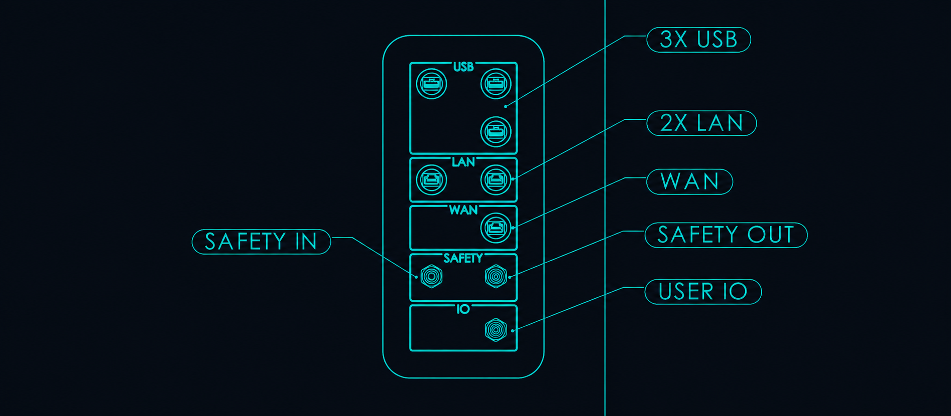
The panel includes:
- USB - three USB ports for accessories and permanently or semi-permanently connected peripherals
- LAN - two Ethernet ports for sensors, cameras, controllers, and other machine-level devices
- WAN - 2.5 Gbit/s Ethernet connection for the customer's network, intranet, MES, or other higher-level systems
- Safety In - dual-channel external safety input for an emergency stop, interlock, or master safety system
- Safety Out - dual-channel dry-contact output indicating the state of the local emergency stop
- User I/O - five PNP-compatible 24 VDC inputs and five relay-switched PNP outputs for sensors, actuators, indicators, and PLC integration
Safety Input#
The Safety In connection allows the Cobot Scanner to be incorporated into an external emergency-stop, interlock, or master safety system.
The input uses two independent normally closed (N.C.) safety channels. For the system to be armed, Channel 1A must be connected to Channel 1B, and Channel 2A must be connected to Channel 2B.
When an external safety circuit is not required, the supplied safety bypass (CE-310190) completes both channels. The bypass uses a field-serviceable connector and can also be rewired for connection to customer safety equipment.
| Item | Specification |
|---|---|
| Machine connector | CE-600183 (Phoenix Contact 1419328) |
| Connector type | 5-position M12 A-coded, female |
| Used contacts | 4; center contact unused |
| Signal | Dual-channel, N.C. |
| Field-serviceable connector | CE-610185 (Manufacturer PN TBD) |
| 3 m cable with flying leads | Cheetah PN TBD (Manufacturer PN TBD) |
Safety Input Pinout#
| Pin | Function |
|---|---|
| 1 | Safety Channel 1B |
| 2 | Safety Channel 2A |
| 3 | Safety Channel 2B |
| 4 | Safety Channel 1A |
| 5 | Not connected |
Each safety channel is completed by a normally closed contact between its A and B terminals:
- Channel 1: pins 4 and 1
- Channel 2: pins 2 and 3
Connector compatibility: The Safety In interface uses a 5-position M12 A-coded socket, with the center contact unused. It can be used with the supplied 4-position male bypass connector or a compatible 5-position male connector or cable.
Safety Output#
The Safety Out connection provides the state of the Cobot Scanner's local emergency stop for integration with a larger safety system.
It provides two independent dry-contact channels. Both contacts are closed during normal operation and open when the local emergency stop is actuated.
| Item | Specification |
|---|---|
| Machine connector | CE-600184 (Phoenix Contact 1419409) |
| Connector type | 5-position M12 A-coded, male |
| Used contacts | 4; center contact unused |
| Signal | Dual-channel dry-contact E-stop status |
| Field-serviceable connector | Cheetah PN TBD (Phoenix Contact 1662968) |
| 3 m cable with flying leads | Cheetah PN TBD (Phoenix Contact 1669835) |
Safety Output Pinout#
| Pin | Function |
|---|---|
| 1 | Safety Channel 1B |
| 2 | Safety Channel 2A |
| 3 | Safety Channel 2B |
| 4 | Safety Channel 1A |
| 5 | Not connected |
Each output channel provides a dry contact between its A and B terminals:
- Channel 1: pins 4 and 1
- Channel 2: pins 2 and 3
Connector compatibility: Requires a 5-position M12 A-coded female mating connector or cable. Pin 5 is not connected.
User I/O#
The User I/O connection provides five general-purpose inputs and five outputs for integrating sensors, actuators, indicators, PLCs, and other external equipment.
The interface uses customer-supplied 24 VDC field power.
The five inputs accept PNP-compatible 24 VDC signals. The five outputs use internal normally-open relays to switch the customer-supplied 24 VDC field power.
| Item | Specification |
|---|---|
| Machine connector | CE-600185 (Phoenix Contact 1442188) |
| Connector type | 12-position M12 A-coded, female |
| Inputs | 5 PNP-compatible 24 VDC inputs |
| Outputs | 5 relay-switched PNP outputs |
| Field power | Customer-supplied 24 VDC and 0 VDC |
| Maximum output current | 1.0 A combined across all outputs |
| 3 m cable with flying leads | Cheetah PN TBD (Phoenix Contact 1430543) |
Note: The 1.0 A output limit is shared across all five outputs. Higher-current loads should be controlled using an external relay or other appropriately rated interface.
User I/O Pinout#
| Pin | Function |
|---|---|
| 1 | External +24 VDC |
| 2 | External 0 VDC |
| 3 | User Input 1 |
| 4 | User Input 2 |
| 5 | User Input 3 |
| 6 | User Input 4 |
| 7 | User Input 5 |
| 8 | User Output 1 |
| 9 | User Output 2 |
| 10 | User Output 3 |
| 11 | User Output 4 |
| 12 | User Output 5 |
Note: Pins 1 and 2 are field-power connections supplied by the customer's external system. The User I/O connector does not provide 24 VDC accessory power from the Cobot Scanner.
Integrated Storage#
The Cobot Scanner includes a front-access storage cabinet with an adjustable internal shelf.
The shelf height can be changed by repositioning four mounting screws. The cabinet can be used to store fixtures, reference parts, setup tools, peripherals, and other equipment associated with the inspection process.
Inspection Bed#
The inspection bed is a configurable mounting surface for fixtures, robot mounting, and application-specific hardware.
It includes:
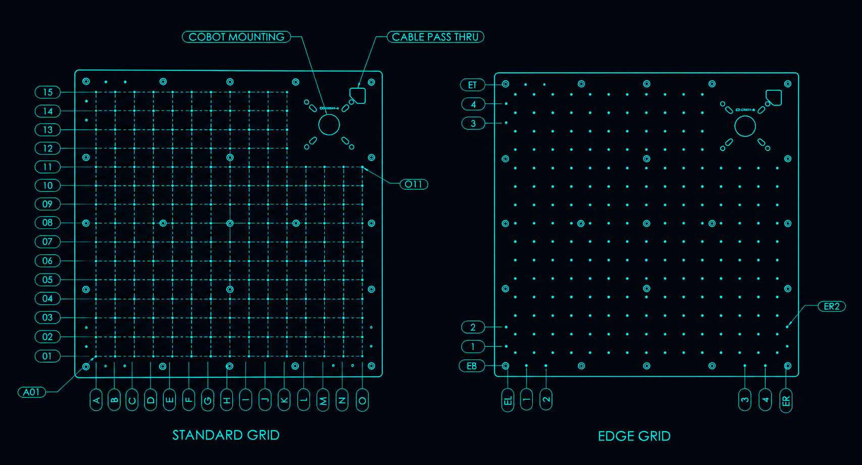
- A 50 x 50 mm grid of M6 threaded holes
- A dedicated cobot mounting area
- A cable pass-through to the inside of the workstation
- Additional edge holes along all four sides for fixture locating and datum features
Hole Addressing#
Each mounting hole has a unique three-character address for use in setup instructions and fixture documentation.
Standard Grid#
Standard grid holes use a column letter followed by a two-digit row number:
- Columns run left to right, from A through O
- Rows run bottom to top, from 01 through 15
- A01 - lower-left standard grid hole
- O11 - column O, row 11
Edge Holes#
Edge holes use a two-letter edge prefix followed by a single-digit position:
- EL1-EL4 - left edge, bottom to top
- ER1-ER4 - right edge, bottom to top
- EB1-EB4 - bottom edge, left to right
- ET1-ET4 - top edge, left to right
For example, ER2 identifies position 2 on the right edge.
The system ships with its intended hardware already installed. Fixtures, robot hardware, and other mounted components should only be moved or reconfigured with guidance from Cheetah.
Control Cabinet#
The Cobot Scanner uses a single-door control cabinet at the rear of the workstation.
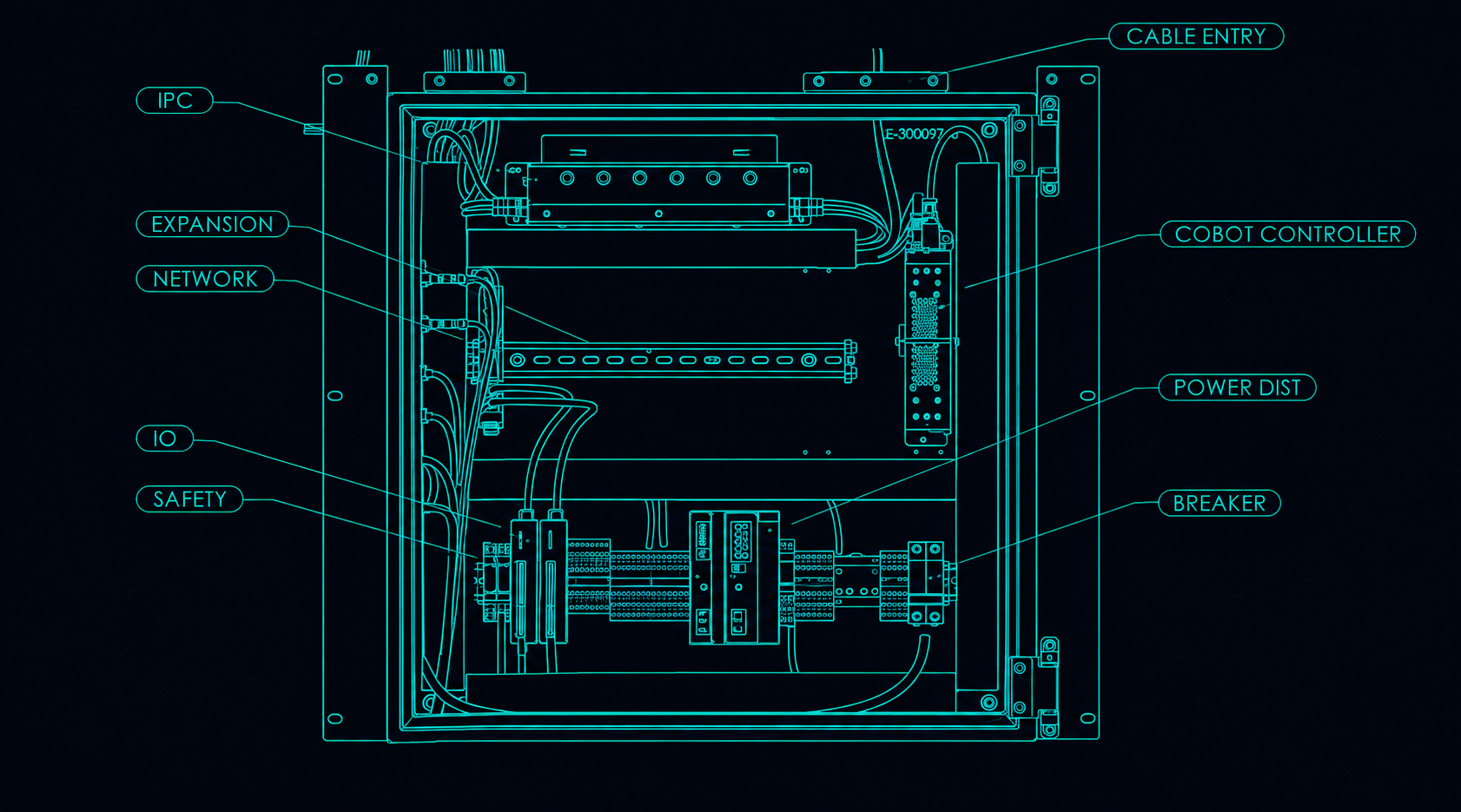
The control cabinet contains the industrial computer, network switch, safety controls, I/O controller, power distribution, and robot controller.
⚠️ WARNING - Risk of electrical shock#
Disconnect workstation power before opening the control cabinet or servicing internal components. Hazardous voltage may be present inside the cabinet whenever the workstation is connected to facility power, even when the system is switched off.
The control cabinet is part of the Cobot Scanner's factory-integrated control system and is not intended as a general-purpose enclosure for customer modification or third-party equipment integration unless otherwise expressly approved by Cheetah. Customer equipment should normally interface with the system through the touchscreen, operator panel, user expansion panel, and documented software interfaces rather than through internal cabinet wiring.
The cabinet includes the system's main breaker, which may require customer access for service or recovery.
The cabinet also provides room for application-specific hardware integrated by Cheetah or installed as part of an approved system configuration. Depending on the application, this can include additional sensor controllers, communications hardware, I/O equipment, or additional robotic and motion-control hardware.
Cable access: A removable panel above the control cabinet provides service access to the internal cable-entry system when application-specific wiring must be routed into the cabinet.
Care and Maintenance#
Key care and maintenance requirements include:
- Keep the workstation and inspection area clean.
- Keep the laser scanner clean and protected from contamination.
- Operate the system in a clean, temperature-controlled indoor environment.
- Refer to robot documentation for robot-specific maintenance requirements.
Technical Specifications#
| Specification | Value |
|---|---|
| Product name | Cobot Scanner |
| Product number | CE-101100 |
| Input power | 110-120 VAC |
| Minimum circuit rating | 15 A |
| Power plug | NEMA 5-15 |
| Touchscreen mounting | Articulated arm, left or right |
| Control cabinet | Rear-mounted, single door |
| Integrated storage | Front cabinet with adjustable shelf |
| Inspection bed | 50 x 50 mm grid of M6 threaded holes |
| User I/O | 5 PNP-compatible inputs, 5 relay-switched PNP outputs |
| User I/O field power | Customer-supplied 24 VDC |
| Maximum User I/O output current | 1.0 A combined across all outputs |
| Customer network | 1 x 2.5 Gbit/s Ethernet |
| Device network | 2 x Ethernet |
| External safety input | Dual-channel; requires two N.C. contacts |
| Local E-stop status output | Dual-channel dry contacts; closed when E-stop is released, open when actuated |
| Robot model | Application-specific |
| Laser scanner | Application-specific |
| Weight | ~225 kg |